Sage Audio Supermos 2

Discussion in 'DIY Discussion' started by Jeff_C, Feb 13, 2014.

  1. Jeff_C

    Jeff_C

    Joined:
    Jan 26, 2014
    Messages:
    26
    Likes Received:
    0
    Location:
    Birmingham
    Hi

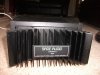
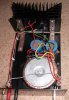
    Is anyone familiar with Sage Audio amplifier kits. I have a pair of Supermos 2 units which were built up into a pair of monobloc power amps. I last used them in about 2001. They were bought April 1989. They were used 1989 to 2001 without any issues.

    I've been reading interesting information on diyaudio forum ( as a guest) because) I'm not registered on that forum.

    I might dig them out and see how they sound now, but I worry about reliability with them. Many other ownner's units seem to have failed. But I remember they did sound very good.

    I stopped using them because I liked the remote control operation on my newer AV set up, but now I have a computer frontend for music I should be able to arrange a remote control of the volume.

    Jeff
     
    Jeff_C, Feb 13, 2014
    #1
  2. Jeff_C

    mjp200581

    Joined:
    Feb 14, 2011
    Messages:
    403
    Likes Received:
    3
    Hi Jeff,

    If a 20+ year old amp is failing the chances are that it is down to some worn-out electrolytic capacitors.

    A few new capacitors could make the unit as good as new again.

    If you're worried about reliability I suggest you have the amp serviced and some new caps fitted. If you don't feel comfortable with the D.I.Y approach try RobHolt on this forum (http://www.bakeraudio.org/)

    If the amp was good in 1989 it will still be good now. Amps haven't really moved on that much.
     
    mjp200581, Feb 14, 2014
    #2
  3. Jeff_C

    Tenson Moderator

    Joined:
    Nov 12, 2003
    Messages:
    5,947
    Likes Received:
    1
    Location:
    Kent, UK
    Does DIY Audio not give clues as to why many have failed? Possibly a certain component is getting too hot? Often it is something like a power resistor being placed too close to an electrolytic cap.
     
    Tenson, Feb 14, 2014
    #3
  4. Jeff_C

    Jeff_C

    Joined:
    Jan 26, 2014
    Messages:
    26
    Likes Received:
    0
    Location:
    Birmingham
    My thoughts were on the Power Supply capacitors (2 x 10,0000uF 80V capacitors for each module) but my very limited knowledge/experience leads me to believe that the capacitors should be OK. As you have found (in your Lenco Amp thread) the capacitance if anything creeps up over time. As for servicing there is not much else to service as the amp module has all components potted in resin within a chamber of the heatsink. The design has died along with Les Sage although there are people who are de-potting the module to learn its secrets. I have took the lids off and the capacitors look OK, no signs of bulging or leakage.

    To summarise as best I can the 2 main threads on diyaudio forum. The claims made by Les Sage about the high quality components used in these modules was grossly exaggerated. Other claims such as Continuous pure Class A operation are also called into question, but the specifications which can be measured seem to be upheld. The Supermos 2 modules have claimed
    Power output 250W into 8 Ohms, 500W into 4 Ohms
    Music Power 380W into 8 Ohms 700W into 4 Ohms
    Max Transient Power 1800W
    Peak Current P-P 80 A
    THD at rated output 0.0001%
    THD at half rated output unmeasurable
    Intermodulation Distortion Unmeasurable
    Crossover Distortion Unmeasurable
    Slewrate >685V/uS
    Freq Response 0.5Hz to 350kHz
    Rise Time <1uS
    Damping Factor 940
    S/N ratio 130 dB
    Sensitivity for full output 1V
    Input Impedance 10k ( i assume 10kOhms)
    Max speaker phase shift drive capability (8 Ohms) 90 degrees

    I'm not pretending that these figures mean that much to me. I am no technical whizz in electronics but the figure that I hear most impresses is the slew rate.

    I did try and paste some links in my original post but for some reason I was unable to. But if anyone wants to check out the mystery surrounding these amp modules and the designer Les Sage just google Les Sage or Sage Audio, there are plenty of results.

    I'll try and upload photos of my modules later and see if any other tips or advice comes in before I try switching them on.

    Jeff
     
    Jeff_C, Feb 14, 2014
    #4
  5. Jeff_C

    Jeff_C

    Joined:
    Jan 26, 2014
    Messages:
    26
    Likes Received:
    0
    Location:
    Birmingham
    There really is nothing to service. The modules only required a power supply and some soldering. The modules are potted with some sort of resin within a housing inside the heatsink. The power supply caps are 2 x 10000uF 80V for each monobloc but there is no evidence of bulging or leaking, and in my very limited knowledge of these things capacitance tends to creep up with age as you have witnessed in your current Leak amp restoration. I suppose it would be best to get them tested/checked though.

    Here's a couple of photos (excuse the dust)
     

    Attached Files:

    Jeff_C, Feb 14, 2014
    #5
  6. Jeff_C

    felix part-time Horta

    Joined:
    Dec 13, 2003
    Messages:
    757
    Likes Received:
    1
    Location:
    dead
    I've never seen one but believe the modules were potted, which wouldn't help if it's a thermal or small-cap-lifetime issue. Equally with the mosfet output stage it could be other things unknown from insufficient gate protection onwards (the 'schematics' I have all have different values for zener protection here for a start) onwards to a stability/oscillation/moisture ingress problem. Who knows.

    I can just about remember the ads for these in the electronics mags when i was at school. Les Sage certainly made some tall claims for their performance, and having found a few 'original' schematics it could be interesting to breadboard the schematic and see what happens. Another task on the 'one-day I will...' projects list.
     
    felix, Feb 14, 2014
    #6
  7. Jeff_C

    Jeff_C

    Joined:
    Jan 26, 2014
    Messages:
    26
    Likes Received:
    0
    Location:
    Birmingham
    Yes the modules are potted. I did try and say this in an earlier post to let mjp200581 know that there was nothing really to have serviced. The only thing to get checked are the power supply caps. They look OK, no signs of bulging or leakage.

    I also tried to post some images but both earlier posts seem to have got lost in the ether. I may have done something wrong. I am new on audiosmile.

    I'll see if I can re-post the images tomorrow.

    Jeff
     
    Jeff_C, Feb 14, 2014
    #7
  8. Jeff_C

    Jeff_C

    Joined:
    Jan 26, 2014
    Messages:
    26
    Likes Received:
    0
    Location:
    Birmingham
    I'm still having trouble posting pictures

    Here's the features list for the Supermos 2 The * denotes these features are exclusive to the Sage Audio Super Series

    *Active Class A O/P
    *Constant Ic, Vce ZERO Distortion Circuitry
    Localised Feedback and Low Overall Feedback
    *Nested Compensation
    *Balanced Circuitry
    *Clean Clipping
    Audiophile Components
    *Matched Semiconductors
    *O/P Emitter Resisters
    *Capacitor Sound Eliminated
    *DC Restoration
    *PSU Feedforward Ripple Elimination
    LED Power On/Fault Trip Indicator

    and here's the specs for the Supermos 2

    Power Output 8 Ohm, 4 Ohm 250W, 500W
    Music Power 8 Ohm, 4 Ohm 380W, 700W
    Max Transient Power 2 Ohm 1800W
    Peak Current P-P 80A
    THD at Rated O/P 0.0001%
    THD at 1/2 rated O/P Unmeasurable
    IntermodulaTION distortion Unmeasurable
    Crossover Distortion Unmeasurable
    Slewrate >685V/uS
    Frequency Response 0.5Hz - 350kHz
    Rise Time <1uS
    Damping Factor 940
    S/N Ratio 130dB
    Sensitivity for full O/P 1V
    Input Impedance 10k (I assume this is 10k Ohms)
    Max Speaker Phase Shift Drive Capability (8 Ohms) 90 degrees

    Most of this means little to me, I'm no electronics person, but it may mean something to the likes of Felix. It does seem like Les Sage grossly exaggerated his claims about the use of high quality components, but my understanding was that all the measurable specs were true (else he would easily have been found out).

    Jeff
     
    Jeff_C, Feb 15, 2014
    #8
  9. Jeff_C

    mjp200581

    Joined:
    Feb 14, 2011
    Messages:
    403
    Likes Received:
    3
    For the pics, try using an image hosting website.

    I use photobucket which works very well. Simply upload your image to photobucket and then copy and paste the link into your post.
     
    mjp200581, Feb 15, 2014
    #9
  10. Jeff_C

    Jeff_C

    Joined:
    Jan 26, 2014
    Messages:
    26
    Likes Received:
    0
    Location:
    Birmingham
    Jeff_C, Feb 15, 2014
    #10
  11. Jeff_C

    mjp200581

    Joined:
    Feb 14, 2011
    Messages:
    403
    Likes Received:
    3
    On photobucket you get a box on the right hand side of the screen with several link options to choose from. Select the bottom option labelled 'Slideshow' and paste that link into your post.
     
    mjp200581, Feb 15, 2014
    #11
  12. Jeff_C

    Jeff_C

    Joined:
    Jan 26, 2014
    Messages:
    26
    Likes Received:
    0
    Location:
    Birmingham
    Jeff_C, Feb 15, 2014
    #12
  13. Jeff_C

    mjp200581

    Joined:
    Feb 14, 2011
    Messages:
    403
    Likes Received:
    3
    Sorry Jeff I've been feeding you incorrect information.

    When you first download an image to photobucket a box with four link options comes up and the last option (bottom) is labelled IMG. It is this link which you need to paste into your post. In fact you can just click next to the IMG link and photobucket with add it to you clipboard.

    For some reason once you have already uploaded a photo the bottom lnk option changes to 'slideshow'.

    I just remembered that I always use the bottom link hence why I gave you the incorrect info.

    I just copied your picture and uploaded it to my own photobucket. With the IMG link selected you'll get this:

    [​IMG]

    I think if you click on one of your saved images to view it full screen the link option go back to showing IMG as an option.
     
    mjp200581, Feb 15, 2014
    #13
  14. Jeff_C

    RobHolt Moderator

    Joined:
    Oct 24, 2004
    Messages:
    4,126
    Likes Received:
    9
    Hi Jeff,

    Cant do much about a potted circuit but if they appear to work ok it might be wise to change the main caps. While capacitance can remain fairly stable, ESR will likely be out of spec on such old parts, especially if they've seen more than 10 years use in the past. I don't always replace large electrolytic PSU caps if they are from a good brand such as Elna, Panasonic, Nichicon etc where I know the amp has seen only a few years use, even if the amp is 10-20 years old. I find heat and ripple from usage is the killer, time sitting unused much less so.

    Given the spec claims, I'd be inclined to go up in value to perhaps 15,000 per side. Two reasons - that size (or 22000) is more appropriate for a such a powerful monster amp, and secondly modern 10,000uf caps will will physically small and requite some mods to the retaining clips.

    Short the input (or connect to your pre with volume at min) shove an 8 Ohm resistors across the output, power up and check for any dc - you don't want to be seeing more than about 50mv. Leave them like that for half an hour or so. If they seem ok, nothing gets too hot and nothing smells bad, have a listen.
     
    RobHolt, Feb 15, 2014
    #14
  15. Jeff_C

    felix part-time Horta

    Joined:
    Dec 13, 2003
    Messages:
    757
    Likes Received:
    1
    Location:
    dead
    Loooking again at the schematics I found of the Supermos 2 it does appear some of the internal parts are running at farily high dissipation at the rated +/-70v rails; for example, there are a pair of resistors (R22, R23) associated with the VAS stage which simply must be running nigh on half a watt each. Not good in a potted module - nowhere for the heat to go, and that's assuming they are rated for 2-3W each in the first place and not basic 1/2w resitors! So it could be a good amp, but a bit fragile as a result of parts choices and build rather than schematic design.

    There are also some very nice touches - the entire input stage and VAS is run off internally smoothed rails (capacitance multiplier on each rail - Q7, Q8); and a cascode VAS. This and the liberal use of current sources around the input stage and output drivers will also make it pretty agnostic to the supply voltages / noise on the main rails.

    Assuming they pass Rob's test, I think I'd consider running these amps at lower voltages in pursuit of longer life - going from, say +/- 70vDC rails down to +/-50vDC will halve the internal heat dissipation, but still allow up to c.110 -120W into 8ohms while having no effect on load-driving capability or bias etc.

    [​IMG]
     
    Last edited by a moderator: Feb 15, 2014
    felix, Feb 15, 2014
    #15
  16. Jeff_C

    Jeff_C

    Joined:
    Jan 26, 2014
    Messages:
    26
    Likes Received:
    0
    Location:
    Birmingham
    [​IMG]

    Many thanks mjp200581. I think I've finally cracked it.

    Rob, thank you for your advice. To test my amps I was going to run them with no input connected, and nothing connected to the output (an infinite load). As I have said I am not an electronics person. Is it *much* better to buy a 8 Ohm resistor to test them as you have said? I can easily short out the input instead of setting up a pre-amp on zero / minimal volume outside.

    I have heard of these modules going "bang" big time. I was going to run an extension lead outside before switching them on just to be on the safe side (if we ever have a dry day). If they do switch on OK and remain stable I wonder whether I will ever have confidence to run them with decent speakers. I will have to decide that before replacing the power supply caps.

    Felix, much of your knowledge is above my level of understanding. But I do recall taking a few windings off the transformer to make sure the power supply was not operating right on the limit of the amp's claimed specs. I cannot remember what the supply is exactly but I think it is likely to be about + / - 67V. I've just checked the Sage paperwork; the max supply voltage recommended by Les Sage for the Supermos 2 is +/- 75V (transformer voltage 53 0 53 AC voltage). As I would not require maximum power I think your recommendation is very good advice. The output curve supplied by Sage shows that +/- 50V would give output of about 125W for a nominal 6 Ohm speaker. (about 110W for 8 Ohm)

    I can say I never cranked up these amps to any great volume. The biggest speaker I ever attached to these amps were suggested to operate at 100W rms and much of the time Mission 751 speakers were attached which are rated at 75W. That may have helped in mine not going bang hadn't it?

    These amps were bought to offer massive headroom and current delivery so dynamic passages in music did not sound compressed. It was a line of thinking at the time to have a big amp for good dynamics.

    Jeff
     
    Last edited by a moderator: Feb 16, 2014
    Jeff_C, Feb 16, 2014
    #16
  17. Jeff_C

    RobHolt Moderator

    Joined:
    Oct 24, 2004
    Messages:
    4,126
    Likes Received:
    9
    Hi Jeff,

    You can test without the resistor but I'd advise shorting the input since that will minimise any noise on the output which might give a misleading reading.

    The advice to run on a lower voltage rail makes perfect sense if you don't require the high output potential. As Martin says, everything is given a far easier time, runs cooler and is less stressed.


    PS: I'll post your foam and damping pads in the morning :)
     
    RobHolt, Feb 16, 2014
    #17
  18. Jeff_C

    Jeff_C

    Joined:
    Jan 26, 2014
    Messages:
    26
    Likes Received:
    0
    Location:
    Birmingham
    I just did a test of these modules. I shorted out the input and put the voltage meter across the output. Smallest scale on the analogue DC Voltage meter selected 10V.

    First the good news. The modules powered up fine. I ran them outside on a mains extension lead for 35 mins and 25 mins (It then started to rain so I terminated the test). They ran with the green LED glowing (denoting all was well). They did not get the slightest bit warm to the touch.

    Now the not so good news.
    What I thought was a low/zero voltage reading across the output, was my old crappy analogue multimeter not working. I tried it beforehand and all seemed OK (but I did not try it with DC Voltage...I know stupid). As the needle never flickered during the test, after the test I tried to get a reading from an AA battery, and could not get a flicker. I've sent off for a new multimeter, and will re-run the test when it arrives.

    But I have to say I'm feeling reasonably confident that these modules are OK.
     
    Jeff_C, Feb 18, 2014
    #18
  19. Jeff_C

    Jeff_C

    Joined:
    Jan 26, 2014
    Messages:
    26
    Likes Received:
    0
    Location:
    Birmingham
    New multi-meter arrived today. I've just re-run Rob's suggested test with the input shorted out, and an infinite load across the output (because I do not have an 8 Ohm resisitor lying around). The voltage reading across the output of each module was :-

    LEFT always < 30mV generally between 27mV and 29mV for the 35 minute test
    RIGHT always < -16mV generally between -13mV and -15mV for the 40 minute test

    I assume that in an ideal world there should be zero DC voltage across the output, and that the negative reading is not important. Please correct me if I am wrong.
     
    Jeff_C, Feb 21, 2014
    #19
  20. Jeff_C

    felix part-time Horta

    Joined:
    Dec 13, 2003
    Messages:
    757
    Likes Received:
    1
    Location:
    dead
    Those are entirely healthy numbers :)

    It's 'nice behaviour' for a power amp output to keep within +/-50mV of 0vDC

    While in fact up to 100mV offset is easily tolerable into a loudspeaker load* - 0.1vDC into 8ohms is just 12mW of dispation so fairly trivial - such higher DC offsets are a good sign something is not right with the amp internally; it might be just a basic /harmless matter of drift from initial set-up, but it should be investigated.

    But your measurements of well under 30-40mV offset observed through and long after intial turn-on is a solid basic healthcheck. The negligible change between intiial turn-on and 30mins later once warm-through is very good - indicates a well-compensated, properly-behaving bias control within the amp. (Lack of an ohmic load doesn't matter for these checks)


    *except, perhaps, an electrostat - increasing DC offsets will cause harmonic distortion due to the input transformer.
     
    Last edited by a moderator: Feb 21, 2014
    felix, Feb 21, 2014
    #20
Ask a Question

Want to reply to this thread or ask your own question?

You'll need to choose a username for the site, which only take a couple of moments (here). After that, you can post your question and our members will help you out.
Similar Threads
Loading...