Leak Stereo 70 amp restoration

Discussion in 'DIY Discussion' started by mjp200581, Feb 2, 2014.

  1. mjp200581

    mjp200581

    Joined:
    Feb 14, 2011
    Messages:
    403
    Likes Received:
    3
    Right then chaps, it's time for another restoration project.

    The unlucky patient is a Leak Stereo 70 integrated amp gifted to me by a friend.

    It's quite a sweet sounding little amp but has had a long working life and now needs some TLC.

    [​IMG]

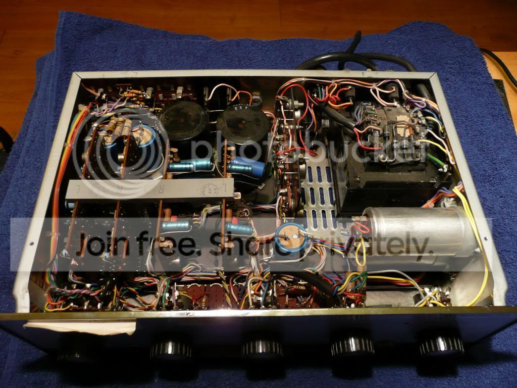
    There are two pre-amp boards (one for each channel) and two power-amp boards. These are the brown coloured boards you can see mounted vertically on the left of the picture. This 'modular' set-up makes fault finding and repair a much simpler process.

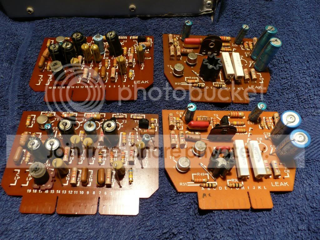
    Here are the boards removed. Pre-amp boards on the left and power amp on the right.

    [​IMG]

    And here is the circuit diagram.

    [​IMG]
     
    mjp200581, Feb 2, 2014
    #1
  2. mjp200581

    mjp200581

    Joined:
    Feb 14, 2011
    Messages:
    403
    Likes Received:
    3
    The first thing I want to do is to replace any tired and worn out electrolytic capacitors. One of the power amp boards has already had a couple of the capacitors replaced in the past which may suggest the others are also near to failing.

    Many of the electrolytics are dimensionally huge by modern standards. The two big black cans look like they would be 22,000uF each but they're actually just 1200uF!!

    Some of them also have unusual non-standard capacitance values such as 64uF, 32uF and 2.5uF.

    Before I place an order for the parts I would like some advice on selecting suitable replacements. I would like to know where the capacitors with unusual values can be safely substituted for more standard values and also where sound improvements may be possible changing the value or the type of capacitor.

    Here is a summary:

    Power amp boards:

    C30 16uF 40v
    C28 10uF 64v
    C29, C32 64uF 64v (would 68uF be OK here?)

    Pre-amp:

    C22 2.5uF 64v (2.5uF is an awkward value would 2.2uF or 3.3uF be OK, film or electrolytic?)

    C11 10uF 10v
    C17, C24, C21, C25 32uF 63v (I'm guessing 33uf would be just fine here)
    C12 100uF 6.3v (It looks like the original cap is marked 6.3v but it could be 63v)

    PSU caps:

    C2, C3, C4 500uF 64v (These could easily be replaced with much higher values if that would be beneficial?)

    C34 2000uF (these are the big silver coloured cans mounted horizontally. They are speaker coupling capacitors so the value must be important, too low a capacitance value will result low frequency roll-off. Again the originals are huge so there is plently of room to increase the value if desirable)

    C6, C7 1200uF 100v (these are the two big filter caps. I could up the value here massively if desired).
     
    mjp200581, Feb 2, 2014
    #2
  3. mjp200581

    mjp200581

    Joined:
    Feb 14, 2011
    Messages:
    403
    Likes Received:
    3
    OK so the non-standard value caps which are going to be difficult to replace are:

    C30 16uF 40v - Will 18uF be OK?

    C29, C32 64uF - Go with 68uF here?

    C22 2.5uF - 2.2uF or 3.3uF would be easy replacements. Can anyone advise me on how critical this value might be? It's a low value cap so I could swap the electrolytic for a film it there'd be any advantage in doing so?
     
    mjp200581, Feb 3, 2014
    #3
  4. mjp200581

    mjp200581

    Joined:
    Feb 14, 2011
    Messages:
    403
    Likes Received:
    3
    It looks to me like C11 is right in the signal path so I'm considering a film cap at this location.

    I've seen some Wima MKS2 10uF films on ebay but they are reasonably expensive and I'm worried that they could be fakes.

    I've managed to find suitable replacements for most capacitors, the only one I'm really not sure about is C22 (2.5uF). This value is hard to get hold of so I'm hoping a more standard value like 2.2uF or 3.3uF would be OK. The trouble is I've no idea how critical this value is? The other option would be to use 0.3uF in parallel with a 2.2uF to get the value of 2.5uF.

    Where's Rob when you need him?
     
    mjp200581, Feb 5, 2014
    #4
  5. mjp200581

    felix part-time Horta

    Joined:
    Dec 13, 2003
    Messages:
    757
    Likes Received:
    1
    Location:
    dead
    Intersting project :)

    Electrolytic caps have always been low-precision parts and subject to huge tolerances, and even today the capacitance values are only nominal - say +/-20% for almost all values. So no, an exact match is defintitely not important, and it's one reason why no-one ever relies on an electrolytic where the value might be critical to the output response (eg filter circuits, RIAA or others)

    If you want a close-ish match that will certainly work, I'd simply round-up the odd values to the nearest -next-standard (e.g basic E12 series which is scaled in decades, roughly: 1.0, 1.2, 1.5, 1.8, 2.7, 3.3, 3.9, 4.7, 5.6, 6.8, 8.4, 10)

    So 2.5uF? Fit 2.7 or 3.3uF. 16uF? try 18, 22 or 27uF.

    I'd round -up the voltage values if in doubt too, too, because modern parts are smaller and will fit, and because the result will have a nice long life. Looking at the circuit it will be fine to use current 63v ratings for the 64v rated parts, very conservative to use 100v where currently 75v and so on.

    I wouldn't worry too much about film caps in the signal path for an amp like this - just use good-quality electrolytics 'in keeping' with the main theme. Elna SilmicII or Panasonic FM or Kemet tantalum work nicely and so will many other comparable parts. if in doubt use a size or two larger capcitance value. These parts won't limit the distortion performance overall. But if you do want to try the Wima MKS2 XLs drop me a pm and I'll happily give you a couple to play with - I grabbed a load some years ago before they went out of wide distribution.
     
    Last edited by a moderator: Feb 5, 2014
    felix, Feb 5, 2014
    #5
  6. mjp200581

    mjp200581

    Joined:
    Feb 14, 2011
    Messages:
    403
    Likes Received:
    3
    Thanks Martin, it sounds like I was going down the right path but it's nice to get some reassurance.

    I spent a while this evening making a list of part numbers from Farnell although I haven't ordered anything yet. I've generally picked a mix of Panasonic FC and Panasonic NHG for the smaller electrolytics which will be mounted on the four 'cards'.

    Like you suggested I had selected the nearest standard value going bigger rather than smaller in each case so 64uF becomes 68uF, 16uF becomes 18uF etc...

    I did think about some Kemet tantalums, are there any particular locatiosn where you feel a tant might have any advantage over an electrolytic in terms of SQ?

    I'd like to take you up on that offer of a couple of 10uF wimas as they seem to be like rocking horse droppings nowadays. I'll send you a P.M.

    The next thing I need to do is to decide which of the bigger electrolytics I want to replace. I have a capacitor tester so I'll yoink them out and see how they measure.

    The original caps are huge in comparison to modern components so there is plenty of scope for upping the values if it is all all desirable.
     
    mjp200581, Feb 5, 2014
    #6
  7. mjp200581

    RobHolt Moderator

    Joined:
    Oct 24, 2004
    Messages:
    4,126
    Likes Received:
    9
    I'd agree with Martin re the caps.
    Quite often the size of electrolytic cap fitted is more determined by price and availability than precise requirement.
    A good example are the dozen or so interstage coupling used in Quad pre amps which are all 100uf. You can use 10uf and still the responses remains flat down to subsonic frequencies, but Quad likely had a stock of many thousands of 100uf caps.....

    Common values are also cheaper to buy, so you tend to see things filled with 100, 47 or 10uf parts which have been purchased in bulk at good discount.
     
    RobHolt, Feb 6, 2014
    #7
  8. mjp200581

    mjp200581

    Joined:
    Feb 14, 2011
    Messages:
    403
    Likes Received:
    3
    Thanks Rob.

    I think I'm about there with selecting replacement parts for the four cards now.

    Tonight I plan to take out the two big speaker coupling caps, the two big black 'cans' and the three smaller blue coloured 500uF caps.

    I'll measure them all for capacitance and ESR and then decide what can be kept and what needs to be replaced.
     
    mjp200581, Feb 6, 2014
    #8
  9. mjp200581

    mjp200581

    Joined:
    Feb 14, 2011
    Messages:
    403
    Likes Received:
    3
    This evening I finished disembowelling the Stereo 70.

    Once removed I gave all the big electrolytics a clean and tested them with my capacitor tester.

    These 1970's capacitors are huge compared to modern ones.

    The two big black ones are the main PSU caps, they are supposed to be 1200uF each but actually tested at 1758uF and 1791uF with ESR's of 0.02 and 0.04 respectively. I think they're good to go again.

    The two silver 'cans' are the speaker coupling caps. I've never heard of 'Daly' capacitors before. They are marked 2000uF but again tested higher at 2318uF each (both exactly the same!) with ESR values of 0.07 and 0.08. Again these seem healthy to me so no need to replace them.

    The three smaller blue caps are marked 500uF and all tested between 502uF and 576uF with ESR values from 0.08 to 0.10

    Again these seem good enough to put back in to me unless anyone advises otherwise?

    [​IMG]

    For comparison the 'small' pale blue cap at the bottom of the pic is actually a modern 4700uF item!

    I gave the casework a good wipe down and everything has been given either a squirt of WD40 or Caig Deoxit as appropriate.

    Looking much better for it.

    [​IMG]
     
    mjp200581, Feb 6, 2014
    #9
  10. mjp200581

    mjp200581

    Joined:
    Feb 14, 2011
    Messages:
    403
    Likes Received:
    3
    My Farnell order arrived yesterday and today I rebuilt the two power-amp cards and the two pre-amp cards with new electrolytic capacitors.

    I used a mix of Panasonic FC, Panasonic NHG some Rubycon YXF and also a couple of Elna Cerfafine which I happened to have in my spares pile.

    Here are the re-capped boards.

    [​IMG]

    The bottom cover for the casework was missing so I fabricated a replacement out of hardboard using the top cover as a template. Spray painted satin black it actually looks quite 'factory' in a 1970's sort of way. Holes in the board allow for decent ventilation and some stick-on rubber feet complete the job.

    [​IMG]

    I want to check and readjust the quiescent current but I've never done this before and I want to check my methodology before I attempt it. I have a copy of the service manual and it sounds simple enough.

    To measure the quiescent current the connecting links between the collectors of T10R and T10L need to be removed. The connecting links are shown in this photo.
    They are the red wires indicated by the tip of the ballpoint pen.

    [​IMG]

    You then hook up an ammeter between the 75v line and the collector(s) (positive to the 75v line) and adjust the quiescent current using potentiometer P5 on the power-amp cards.

    The service manual gives dire warnings about not turning on the amp without either the connecting links or an ammeter in place.

    So.....does this sound correct?

    1) Remove connecting link to T10R but leave link to T10L in place.
    2) Connect the ammeter (my cheap multimeter) as described with positive probe to 75v line and negative probe to collector of T10R
    3) Turn on the amp and adjust the quiescent current of the right channel to the specified 30mA
    4) Once adjusted, turn off the amp and reconnect the connecting link to T10R collector.
    5) Remove connecting link to T10L and then follow the rest of the above procedure for the left channel.

    I'd like to confirm the above is correct before I give it a try!
     
    mjp200581, Feb 11, 2014
    #10
  11. mjp200581

    mjp200581

    Joined:
    Feb 14, 2011
    Messages:
    403
    Likes Received:
    3
    Well I just had a go at setting the quiescent current.

    My method was correct so no blown transistors but I'm struggling to get a satisfactory setting on the left channel.

    The service manual specifies 30 to 35mA and I was able to get it spot on for the right channel but the left doesn't want to play ball. The lowest setting I can achieve on the left channel is about 42mA with the trim-pot on its minimum setting.

    I think the trim-pot is to blame, it's a bit grotty looking and the carbon track is badly pitted.

    I want to replace both trim-pots with new ones but I can't find any in the right size which will be drop-in replacements.

    Does anyone know where I could get some?

    They are 220R with a pitch of 5mm between each lead and the leads are all in a straight line rather than staggered.
     
    mjp200581, Feb 13, 2014
    #11
  12. mjp200581

    mjp200581

    Joined:
    Feb 14, 2011
    Messages:
    403
    Likes Received:
    3
    I gave up trying to find some trim-pots which would be a direct 'drop-in' replacement and I've ordered a couple of sealed multi-turn 10mm ones which I should be able to get to fit. They ought to be much more accurate and reliable than the originals. Once they arrive I'll have another go at setting the quiescent current.

    I've been reading around on the web and I've found a few recommendations for upping a few capacitor values:

    C32 - As standard this is 64uF and I've just swapped it out for a 68uF. I've read people referring to this cap as the "bootstrap" capacitor and suggesting 220uF as an upgrade.

    C22 - As standard this is 2.5uF and I've just installed a 3.3uF. Again some people are suggesting 10uF here.

    Any comments on the above?

    If the image of the schematic which I posted earlier isn't big enough you can view it here.

    http://www.magafox.com/tubeamps/Leak Manuals/LEAK STEREO 70 COMBINED.pdf
     
    mjp200581, Feb 14, 2014
    #12
  13. mjp200581

    felix part-time Horta

    Joined:
    Dec 13, 2003
    Messages:
    757
    Likes Received:
    1
    Location:
    dead
    C33 - don't worry about it. looks good to me.

    C32 is indeed a bootstrap, but looking at the values of resistors around it, it already has a sub-2Hz rolloff so going larger isn't going to help anything /make a difference in the bass.

    If you haven't met one before, a bootstrap is an interesting alternative to a current source you'd probably choose for this role today. One end of the cap C32 is driven from the amplfier output, so at audio frequencies, the other end voltage 'follows' the output signal (because the charge on the cap will remain near-constant). This means the voltage across R45 is held very nearly constant, and that means very nearly constant-current through the bias spreader (the two diodes and the 220ohm pot).

    This was much heaper in the 60s than another couple of transistors, and remains really quite effective*. With c32=68uF and R44=1K above, your Leak works this way down to below 2Hz, i.e. to below the full range of the amplifier output. Nothing to be gained by going larger there, I think.


    *even if it looks suspiciously like positive feedback it's not a stability risk in a solidstate amp. Incidentally Hugh Dean / Aksa (for one, amongst others) retains the use of bootstrap caps instead of CCS in their amplifier modules on grounds of listening pleasure / what it does to the distortion profile when handled carefully; so it's not a bad thing by any means.
     
    felix, Feb 14, 2014
    #13
  14. mjp200581

    mjp200581

    Joined:
    Feb 14, 2011
    Messages:
    403
    Likes Received:
    3
    Thanks Felix, superb technical advice as ever.
     
    mjp200581, Feb 15, 2014
    #14
  15. mjp200581

    mjp200581

    Joined:
    Feb 14, 2011
    Messages:
    403
    Likes Received:
    3
    The new trim pots arrived a few days ago and are now installed.

    I couldn't find new trimmers with the same dimensions as the originals but some 10mm (3/82) small sealed single turn trim pots with the legs spread apart does the job just fine.

    The manual states a quiescent current of 30mA but the minimum I could achieve on the left channel was 33mA even with the trim pot on its minimum setting.

    I have set right channel to 33mA to match the left which puts the trimmer at about 1/3rd of the way along its adjustment range. I have no idea why there should be such a difference between the channels.

    So that makes the restoration complete (for now anyway). Another 1970's amp saved from the scrap heap!:)

    I've been listening today and it certainly sounds better for a bit of TLC. I bought a 5 pin DIN to 3.5mm lead which means I can connect my ipod via the tape in socket on the front fascia. Connected this way with the tape monitor switch selected allows you to listen with the pre-amp boards and tone controls bypassed for a small but worthwhile improvement in clarity.

    I'm enjoying the sound of this little amp. I really like the way it does percussion and it does a great job of bass guitars. The mid-range is a little 'hollow' (if you know what I mean) but that could be the speakers which are just little 2-way Wharfedale Super Diamond bookshelf speakers. I haven't been brave enough to ask it to drive my big AOS transmission lines.

    [​IMG]
     
    mjp200581, Feb 24, 2014
    #15
  16. mjp200581

    mjp200581

    Joined:
    Feb 14, 2011
    Messages:
    403
    Likes Received:
    3
    Gentlemen, I need some help please! To be more specific I need some help getting the quiescent current settings sorted but more on that in a moment....

    I've been doing some more restoration/upgrade work on this amp today. For starters I've swapped C11 on the pre-amp board to some lovely Elna Silmic II capacitors. C11 is directly in the signal path at the input of the pre-amp boards so I figured there would be a benefit to using a 'nice' sounding cap. I've used Silmics before as DC blocking capacitors at the output of CD players and they are lovely sounding capacitors (for electrolytics!).

    [​IMG]

    10uF Rubycon out and 10uF 100v Elna Silmic in....

    [​IMG]

    I also got around to replacing the three blue coloured 500uF big electrolytics (C2, C3 and C4). I used these Panasonic caps which are conveniently the same diameter as the originals so fit in the existing sockets. They are 250v and 105C rated so should last ages. I couldn't find any decent 500uF replacements so the capacitance has been increased to the next standard unit which is 560uF.

    [​IMG]

    So that's all good but I'm really struggling with the quiescent current settings. The manual specifies 30mA and whilst I can get this setting spot on with one channel the other channel will not go lower than about 50mA even with the trim-pot on the minimum setting. If you swap the cards over the problem swaps sides so the issue is not with the output devices.

    Is is possible that some of the carbon resistors have drifted in value causing the imbalance? If so, are any particular resistors likely to be the prime suspects? Here is a schematic:

    [​IMG]

    This problem is driving me crackers and I'd really appreciate some advice.
     
    mjp200581, Sep 2, 2014
    #16
  17. mjp200581

    felix part-time Horta

    Joined:
    Dec 13, 2003
    Messages:
    757
    Likes Received:
    1
    Location:
    dead
    With the amp unplugged so you can check dc conditions -

    I would check R32, R53 for being too small a value (below 0.5ohm - but check what your multimeter reads with its leads sjhorted first, often thats about 0.2-0.3ohms alone) and R49 (22K) in case its drifted low (and is turning-on T11 a bit hard.)

    Measured from one end to the wper, can you see the full range of 0-200ohms or so on the preset P5?

    That's where I'd start :)
     
    felix, Sep 2, 2014
    #17
  18. mjp200581

    mjp200581

    Joined:
    Feb 14, 2011
    Messages:
    403
    Likes Received:
    3
    Hi Martin, thanks for the help.

    I'm assuming you mean R52 and R53 (the schematic is a little hard to read). These are 'concrete' type resistors so are unlikely to have drifted. I whipped them out and they both measure very close to 1.5 Ohm.

    R49 - The values for the Stereo 70 are actually the ones shown in red, so R49 should be 33K. Removed from the circuit it measures 32.9K.

    Potentiometer P5 is also good. I replaced these recently and it measures almost 0-200 Ohm.

    Any further suggestions??
     
    Last edited by a moderator: Sep 3, 2014
    mjp200581, Sep 2, 2014
    #18
  19. mjp200581

    felix part-time Horta

    Joined:
    Dec 13, 2003
    Messages:
    757
    Likes Received:
    1
    Location:
    dead
    Oh well...

    Have either of R46 or R47 drifted rather higher than 220R ? (i.e. the emitter resistors for drivers T8 and T9)

    I've just noticed there are a few voltage checks on that diagram - worth ensuring your problem channel is close-ish to the values relevant for your version of the amp around teh output stage., eg '43vdc at the anode of C32'.
     
    felix, Sep 4, 2014
    #19
  20. mjp200581

    mjp200581

    Joined:
    Feb 14, 2011
    Messages:
    403
    Likes Received:
    3
    We may have something:

    R46/R47 are 267R and 244R and are supposed to be 220R.

    I'll do the voltage checks at C32 anode later and report back.

    I'm tempted to simply do a precautionary replacement of all of the resistors on each board. It's only 16 resistors per board so won't break the bank. If I only replace the carbon tube types it will only be 6 resistors per board.

    They look about 0.5W size to me. Would 0.5W metal films be a suitable choice?
     
    mjp200581, Sep 5, 2014
    #20
Ask a Question

Want to reply to this thread or ask your own question?

You'll need to choose a username for the site, which only take a couple of moments (here). After that, you can post your question and our members will help you out.