You are using an out of date browser. It may not display this or other websites correctly.
You should upgrade or use an alternative browser.
You should upgrade or use an alternative browser.
Leak Stereo 70 amp restoration
- Thread starter mjp200581
- Start date
- Joined
- Feb 14, 2011
- Messages
- 403
- Reaction score
- 3
I did some voltage checks on the power-amp cards:
At anode of C29 - 54vdc (Left channel), 56vdc (right). Schematic indicates 69v
Anode of C32 - 73.6v L, 74v R. Schematic says 69v
After P5 by junction of T7/T9 - 33.5 vdc L, 34.8 vdc R (schematic says 36v)
But then while I had the cards back in place I decided to have another go at setting the quiescent current and voila I managed to set both channels to the specified 30mA with no problems!!
I haven't replaced any more components so it's rather odd that it seems to have 'fixed' itself. I did remove R46 and R47 though and I didn't make a effort to put them back into the original positions, so R46 and R47 may have been swapped around. Also the cards are notorious for having dodgy connections and simply removing and reinstalling the cards a few times may have fixed a poor connection somewhere.
The good news is that it's all back together and working perfectly again. The bad news is that I don't know what the problem was. I'm still tempted to replace some of the resistors which have drifted as precautionary measure but this can wait for now.
Now that is interesting - giving the card connectors a good scrub is probably worthwhile.
Also reassuring - it's obviously not too sensitive to component actual values, and I really wouldn't worry too much about them. Nice the amp is working again as it should - enjoy it")
Also reassuring - it's obviously not too sensitive to component actual values, and I really wouldn't worry too much about them. Nice the amp is working again as it should - enjoy it
- Joined
- Feb 14, 2011
- Messages
- 403
- Reaction score
- 3
I've been slowly working my way through the Leak Stereo 70 replacing all of the ancient electrolytics which are no doubt past their best by now.
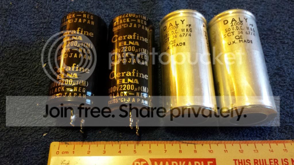
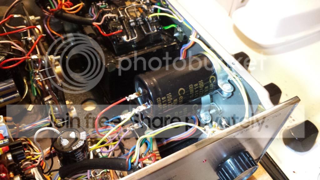
For the speaker coupling capacitors I was very lucky to find a pair of 2200uF 100v Elna Cerafine on ebay. They are even the same diameter as the originals so will conveniently fit into the existing 35mm sockets. Mmm lovely.
The Elnas in their new home.
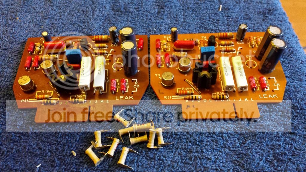
I also couldn't resist swapping all the the tube type carbon resistors on the power amp cards. The originals had all drifted quite a bit (high in most cases) and for the pennies it was going to cost I decided to replace them. I used 0.5w rated PRP metal films. I left all the 'normal' shaped originals resistors untouched as these don't seem to have drifted anything like as much.
And I was very much looking forward to listening to it this evening......only I can't because I've broken it!!
I know what happened (and it's rather too embarrassing to admit to). The long and short of it is that it looks looks like I've blown the two T-03 output devices on the left channel. Balls!
The originals are 2N3055 and a quick check on Farnell shows that they stock a few different varieties. All are 15A, 115W and 60v rated but I have a choice of 2.5MHz, 3MHz or 800KHz transitions frequency. I assuming faster is better?
I'd be grateful for any advice on selecting the best ones for the job. There may be other types which could be an upgrade over the 2N3055.
Thanks in advance.
For the speaker coupling capacitors I was very lucky to find a pair of 2200uF 100v Elna Cerafine on ebay. They are even the same diameter as the originals so will conveniently fit into the existing 35mm sockets. Mmm lovely.

The Elnas in their new home.

I also couldn't resist swapping all the the tube type carbon resistors on the power amp cards. The originals had all drifted quite a bit (high in most cases) and for the pennies it was going to cost I decided to replace them. I used 0.5w rated PRP metal films. I left all the 'normal' shaped originals resistors untouched as these don't seem to have drifted anything like as much.

And I was very much looking forward to listening to it this evening......only I can't because I've broken it!!
I know what happened (and it's rather too embarrassing to admit to). The long and short of it is that it looks looks like I've blown the two T-03 output devices on the left channel. Balls!
The originals are 2N3055 and a quick check on Farnell shows that they stock a few different varieties. All are 15A, 115W and 60v rated but I have a choice of 2.5MHz, 3MHz or 800KHz transitions frequency. I assuming faster is better?
I'd be grateful for any advice on selecting the best ones for the job. There may be other types which could be an upgrade over the 2N3055.
Thanks in advance.
Oh dear!
The 2N3055 is the horsehoe crab of power transistors - it's been around forever.
Which version to get is a good question - my instinct is to not buy the fastest iteration; unless the amp is compensated for it already, then you may run into percnicious oscillation problems needing a scope to check (esp. if the transistors are remote from the main board and linked by flying wires, as some old amps are)
Going for the nearest equivaent to that available when the amp was designed (the slow one, inevitably) is undoubtedly safe. It really won't make for an measurable let alone audible difference.
In all honesty all three options will probably work fine in a simple amplifier like this, but if you don't have a means to verify matters, play safe.
*Edit to add - looking again at the schematic (with a simple single-ended input transsitor) part C31 is the 'compensation' cap to maintain internal stability. 400pF is a mighty value by later amp standards! This amp will be very, very stable, but equally, there's little point fitting 'faster' ouput devices - because the internal bandwidth of the amp is so firmly strapped-down. So answer is, just buy the best-value reputable parts for the output transistors. PS I'd buy enough for both channels, and put the spares aside for a rainy day.
Last edited by a moderator:
- Joined
- Feb 14, 2011
- Messages
- 403
- Reaction score
- 3
Thanks for the advice Martin.
I did a little homework and found that the Quad 303 used a special 'selected' version of the 2N3055 (part number38494).
The MJ15003 seems to be a popular choice as a replacement for the 38494 amongst Quad 303 owners.
I'm going to send Robert a PM to see if he has any particular advice on sourcing good quality 2N3055 equivalents. I expect he's replaced lots over the years!
- Joined
- Feb 14, 2011
- Messages
- 403
- Reaction score
- 3
No reply from Rob yet but I've found that with the top and bottom covers removed it's possible to read the lettering on the original output transistors. They are marked 'ST Malaysia'.
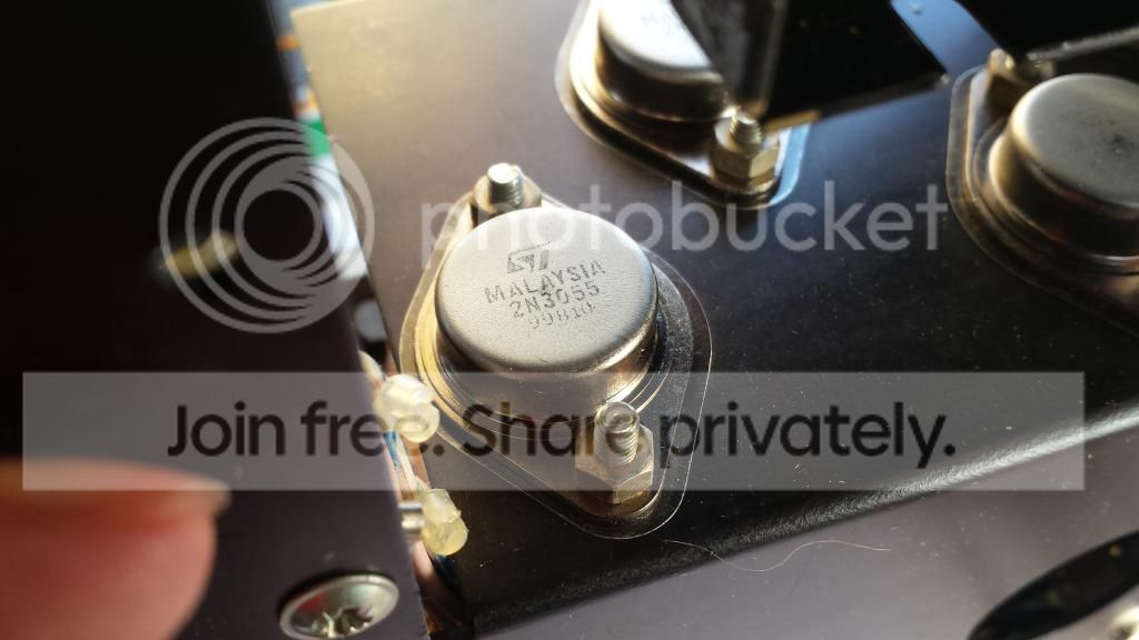
Farnell has ST branded 2N3055's in stock so I may just go for those as they're cheap as chips. They also have 'ON Semi' branded components which I have read are the same as Motorola and are supposedly of good quality.
While I'm putting a Farnell order together I'll also replace the two big filter caps (C6 and C7). The originals are marked up as 1200uF but measure at more like 1700uF.
I'll probably go with 2200uF Panasonic TS-ED (order code 1198616) unless anyone has any better suggestions?
- Joined
- Feb 14, 2011
- Messages
- 403
- Reaction score
- 3
In the end I purchased some MJ15003 transistors in the hope that the MJ15003 will give me better reliability than standard (i.e non-selected) 2N3055.
Worryingly there seem to be an awful lot of counterfeit MJ15003 transistors on the market! There is a very helpful guide on the ESP website here:
http://sound.westhost.com/fake/counterfeit-p1.htm
I bought mine from Farnell so hopefully they are the genuine. They are ON Semi branded and the serial numbers and typeface seem OK according to the guide on the ESP website. They were also reassuringly expensive at about £4 each.
I have just checked with my multimeter that they all test correctly as a pair of diodes from B to E, B to C and then back again with the probes reversed.
I then tested them all with the HFE function on my multimeter. They tested at 51, 55, 62 and 67.
Q1: I know that the HFE reading given by my multimeter can't be expected to be the same as the data sheet but do those figures seem reasonably well matched?
Q2: Should I use 51+67 on one channel and 55+62 on the other channel?
Q3: Is it worth buying more and then sorting them into a matched set?
I then tested the original 2N3055 transistors taken from the good (not blown) channel and they tested at 14 and 258. What the hell is that all about?!
The good news is that I have finished fitting the new Panasonic filter caps together with their new capacitor clamps.
Hfe figures don't matter at all for matching, it's Vbe that matters - if matching is critical (and it's not for a quasi-cmop o/put like the Leak)
Most hfe tests on meters are at ridiculously low collector currents like 0.1 -1ma anyway so not representative for power transistors anyway. I'd not worry any further - pick two from four and use as you like. The amp's performance is defined by feedback anyway (the benefit and purpose of feedback )
Most hfe tests on meters are at ridiculously low collector currents like 0.1 -1ma anyway so not representative for power transistors anyway. I'd not worry any further - pick two from four and use as you like. The amp's performance is defined by feedback anyway (the benefit and purpose of feedback
)- Joined
- Feb 14, 2011
- Messages
- 403
- Reaction score
- 3
OK thanks, this is all new to me.
I'm just waiting for some silicone pads to arrive and then I can get the new transistors fitted.
I just changed the two small trim-pots on the power amp cards to sealed Bourns multi-turns as I found it tricky to set the quiescent current accurately with the single turn types.
Here is what the inside of the dead transistors looks like:

Last edited by a moderator:
- Joined
- Feb 14, 2011
- Messages
- 403
- Reaction score
- 3
It's fixed
Here is a final pic
So to summarise:
Sounds much nicer for it.
Thanks for all of the help!!
Here is a final pic

So to summarise:
- New base board and rubber feet.
- New Panasonic TS-ED power supply capacitors.
- New electrolytics on the pre and power amp cards (mainly Pansonic FC, Elna Silmic II and Elna Cerfine)
- Sealed multi-turn trim-pots at P5 on power amp cards.
- Elna Cerafine speaker coupling caps.
- MJ15003 output transistors (ON Semi)
- A sprinkling of new resistors (PRP metal film 1%)
- And finally a few squirts of Caig Deoxit and WD40.
Sounds much nicer for it.
Thanks for all of the help!!
Hi,
Glad to know that I found this thread about Leak Stereo 70 parts upgrade/replacements. I just bought one 2nd hand of course and in working order and thinking doing some replacements/upgrades. I don't have an electronics degree but just have some experience when it comes to soldering. To make it short, I just want to get an idea on what upgrade/replacement you had in this AMP which is on the top 3 list which made a huge difference when it comes to sound as want to follow that step as well. thank you so much.
Leo
- Joined
- Feb 14, 2011
- Messages
- 403
- Reaction score
- 3
Hi Leo,
Welcome to the forum.
To begin with I'd concentrate on restoring the amp back to its 'as new' level of performance rather than trying to make any big improvements to the original design. Your amp already works so that's a great start!
On an old amp like this the usual place to start is with the electrolytic capacitors. Over time these dry out causing their performance to deteriorate. Visually examine all of the capacitors in situ for signs of bulging and/or leaking and if you see any damaged capacitors they must be replaced.
I would also recommend that you measure and if necessary adjust the quiescent current on both channels. If you find it hard to get a satisfactory setting replacing the old flaky trimpots with new sealed multi-turn types may make the job much easier. Make sure you follow the procedure carefully or you'll risk damaging the output devices.
After this you can start to either test the remaining electrolytic capacitors with a capacitor tester or launch into a wholesale re-cap of the amp which may be unnecessary but won't break the bank.
- Joined
- Mar 10, 2018
- Messages
- 9
- Reaction score
- 1
Hi Leo,
Welcome to the forum.
To begin with I'd concentrate on restoring the amp back to its 'as new' level of performance rather than trying to make any big improvements to the original design. Your amp already works so that's a great start!
On an old amp like this the usual place to start is with the electrolytic capacitors. Over time these dry out causing their performance to deteriorate. Visually examine all of the capacitors in situ for signs of bulging and/or leaking and if you see any damaged capacitors they must be replaced.
I would also recommend that you measure and if necessary adjust the quiescent current on both channels. If you find it hard to get a satisfactory setting replacing the old flaky trimpots with new sealed multi-turn types may make the job much easier. Make sure you follow the procedure carefully or you'll risk damaging the output devices.
After this you can start to either test the remaining electrolytic capacitors with a capacitor tester or launch into a wholesale re-cap of the amp which may be unnecessary but won't break the bank.
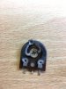
Hi- I read your thread as Ive had a couple of these for many years, one worked and one needed new drivers- they had been in my loft for about 15 years and boredom set in, so i decided to repair the duff one. one channel was dead due to blown drivers- I repalced them and couldnt get the IQ correct. It was the trimpot- same as you found.
I turned it around as it was measuring 560 ohms out of circuit- not 200! The outputs were getting v hot, but it was working- IQ was about 1/2 an amp...
For anyone reading this, its a quick-fix as 200 ohm 1/2w trimmers are not that easy to come by.
You will note from the wring diagram that one leg is storted to the wiper- so you can simple swap it around and use the carbon track thats not heat/age damaged.
I re-capped it on the power boards and its running nicely!
Attachments
Hi...i am a new user here. I agree that Electrolytic caps have always been low-precision parts and subject to huge tolerances, and even today the capacitance values are only nominal - say +/-20% for almost all values. So no, an exact match is defintitely not important, and it's one reason why no-one ever relies on an electrolytic where the value might be critical to the output response.
- Joined
- Mar 10, 2018
- Messages
- 9
- Reaction score
- 1
the transistors on the preamps are fairly tolerant of substitution Ive found- Ive got a couple of ST70s and considering they are pre 1970- Im amazed they still work with minimal mainteance. Not like newer 1980 amps with modular intergrated amps (that are difficult to repalce due to the form-factor)
Attachments
- Joined
- Mar 3, 2023
- Messages
- 4
- Reaction score
- 0
The first thing I want to do is to replace any tired and worn out electrolytic capacitors. One of the power amp boards has already had a couple of the capacitors replaced in the past which may suggest the others are also near to failing.
Many of the electrolytics are dimensionally huge by modern standards. The two big black cans look like they would be 22,000uF each but they're actually just 1200uF!!
Some of them also have unusual non-standard capacitance values such as 64uF, 32uF and 2.5uF.
Before I place an order for the parts I would like some advice on selecting suitable replacements. I would like to know where the capacitors with unusual values can be safely substituted for more standard values and also where sound improvements may be possible changing the value or the type of capacitor.
Here is a summary:
Power amp boards:
C30 16uF 40v
C28 10uF 64v
C29, C32 64uF 64v (would 68uF be OK here?)
Pre-amp:
C22 2.5uF 64v (2.5uF is an awkward value would 2.2uF or 3.3uF be OK, film or electrolytic?)
C11 10uF 10v
C17, C24, C21, C25 32uF 63v (I'm guessing 33uf would be just fine here)
C12 100uF 6.3v (It looks like the original cap is marked 6.3v but it could be 63v)
PSU caps:
C2, C3, C4 500uF 64v (These could easily be replaced with much higher values if that would be beneficial?)
C34 2000uF (these are the big silver coloured cans mounted horizontally. They are speaker coupling capacitors so the value must be important, too low a capacitance value will result low frequency roll-off. Again the originals are huge so there is plently of room to increase the value if desirable)
C6, C7 1200uF 100v (these are the two big filter caps. I could up the value here massively if desired).
I just got one of these and i need to replace the capacitors can i ask where did you get your caps from farnel ?
- Joined
- Mar 3, 2023
- Messages
- 4
- Reaction score
- 0
My Farnell order arrived yesterday and today I rebuilt the two power-amp cards and the two pre-amp cards with new electrolytic capacitors.
I used a mix of Panasonic FC, Panasonic NHG some Rubycon YXF and also a couple of Elna Cerfafine which I happened to have in my spares pile.
Here are the re-capped boards.
The bottom cover for the casework was missing so I fabricated a replacement out of hardboard using the top cover as a template. Spray painted satin black it actually looks quite 'factory' in a 1970's sort of way. Holes in the board allow for decent ventilation and some stick-on rubber feet complete the job.
I want to check and readjust the quiescent current but I've never done this before and I want to check my methodology before I attempt it. I have a copy of the service manual and it sounds simple enough.
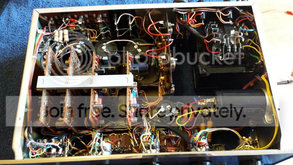
To measure the quiescent current the connecting links between the collectors of T10R and T10L need to be removed. The connecting links are shown in this photo.
They are the red wires indicated by the tip of the ballpoint pen.
You then hook up an ammeter between the 75v line and the collector(s) (positive to the 75v line) and adjust the quiescent current using potentiometer P5 on the power-amp cards.
The service manual gives dire warnings about not turning on the amp without either the connecting links or an ammeter in place.
So.....does this sound correct?
1) Remove connecting link to T10R but leave link to T10L in place.
2) Connect the ammeter (my cheap multimeter) as described with positive probe to 75v line and negative probe to collector of T10R
3) Turn on the amp and adjust the quiescent current of the right channel to the specified 30mA
4) Once adjusted, turn off the amp and reconnect the connecting link to T10R collector.
5) Remove connecting link to T10L and then follow the rest of the above procedure for the left channel.
I'd like to confirm the above is correct before I give it a try!


Im trying to test the current on mine also have you a picture of the collecters where you put the negative probe i have found the 75v positive line ok.