Progress on the new Audiosmile loudspeaker

RobHolt

Moderator
Joined
Oct 23, 2004
Messages
4,126
Reaction score
12


Seen here next to the Rogers LS3/6, the new AS model is slightly shorter and deeper.


Built by developing the ideas pioneered by the BBC Research department, the new LS3/6 styled model is sounding very promising indeed.

Using a developed version of the thin wall damped cabinet with selective light coupling rods (not bracing) the overall qualities of the BBC approach has been retained in this ply cabinet construction but with much improved cabinet decay characteristics.

Superb phase coherence is achieved via the crossover with the waveguide mounted tweeter integrated into the mid dome mounting plate.

Sensitivity on the prototype is 91dbw with a valve amplifier friendly nominal 8 Ohm load.

The finished model will also use front baffle absorption to correct the effects of diffraction, making this a model designed for use fully clothed with no deleterious effects.

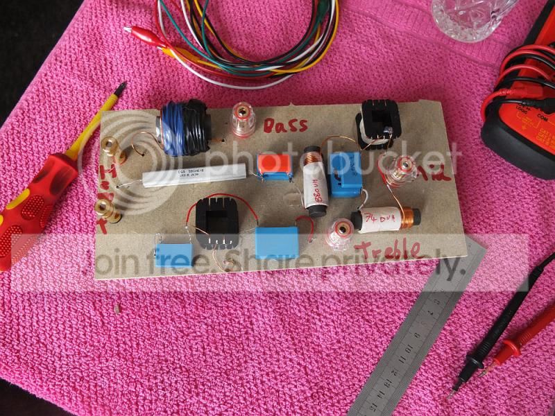
Seen in the photo above is the crossover design stage. Software uses circular convolution and a 3-way active arrangement to predict what the passive crossover will do before actually building it and making final tweaks.

More very soon so keep watching.
 
Now that looks interesting! :)

If you need a cheap accelerometer to test cabinet locations of the tie rods with - well I've always had excellent results recording guitar by blu-tac'ing even very cheap earbuds face-down to the body, fed into a mic preamp.

Given you can find dynamic earbuds for about £5 a pair in most supermarkets these days, £30 will get you a dozen 'sensors' cheap ;)

Off the top of my head I suspect the tie rods want a resistive, ie lossy connection the wall on at least one end for dropping the cab 'Q' / a broader damping effect - if that's what you are after.
 
Last edited by a moderator:
I used to use pietzo speakers like from musical xmas cards as vibration sensors. Got a couple of nice ones from Digi-Key recently though. ACH-01 and built a metal cased battery powered high gain head-amp.
 
Analysing the modal pattern of the cabinet panel using a grid system and Measurement Specialties ACH-01 accelerometer.

It's possible to simulate the modal behaviour of the panel in software, but the complexities of damping and panel fixing to the cabinet make it more accurate to really measure the behaviour.

Panel-Analysys.jpg
 
Pssive first, but I might do a digital active version with something like the MiniDSP box.

Regarding the cabinet shape it just seems more proportioned IMO. It should still work with existing LS3/6 stands as the tweeter is much the same height and the base is just a bit deeper.
 
If you want to do the XO in DSP, think about something like the Najda , you could sell to the AVI market - all you need is a digital source, or you can integrate analog sources.
 
That looks brilliant Markus, I hadn't seen it! Might be perfect for another speaker too, that I was thinking I'd have to use a PC XO.
 
I believe Pete/I should coco uses one on his active horn speakers. There's a thread somewhere on Wigwam.

More here:

http://www.diyaudio.com/forums/digital-line-level/215379-dsp-xover-project-part-2-a.html

http://www.diyaudio.com/forums/digital-line-level/234773-najda-builds-resource-list.html

http://www.avsforum.com/t/1466915/najda-dsp-board-for-loudspeaker-applications

http://www.diy-hifi-forum.eu/forum/showthread.php?p=75986

Is there a compelling reason for offsetting the tweeter to the side, relative to the larger dome (I guess that's a 2" one?)? Asymmetrical designs end up costing a lot because customers demand handed versions, purely for reasons of aesthetics; and they won't care if you recommend running the speakers with their socks on.

Alternatively, you could think about manufacturing a mounting plate that allows different orientations, like German manufacturer Nubert does for its nuLine series:

nuline-34_platin_th.jpg


If you do the baffles on your in-house CNC lathe, the economics may be different, of course.
 
Last edited by a moderator:
Hi Markus,

It's not an issue to do 'handed' baffle on the CNC. The tweeter is off-set to minimise baffle diffraction. The different frequency of operation for the tweeter and midrange mean they both have slightly different optimal placement.

Mid-dome is 2" and will run from around 800Hz to 4KHz.
 
Did the top panel analysis yesterday. Interestingly, even though the depth of the top and bottom are the same as the sides, the position of the main resonances are entirely different.

I'm using 6mm thickness panels to link each opposing cabinet wall at the main points of resonance. 6mm panels seem to be the ideal mixture of covering the largest areas of resonance by their edge length, while not adding much stiffness to the cabinet walls due to being very thin. This method creates a pathway for energy to pass between opposing cabinet walls. The walls are moving in opposite phase to each other and so we are basically injecting anti-phase energy into each panel at the points of resonance and they cancel out. It's far more effective than just trying to make the cabinet stronger and stiffer.
 
Things are progressing well. I've finished the cabinet design with the 'cross-links' in optimal placement. The results are very good. The aim of the BBC design is to push the cabinet wall resonances low in frequency by not using stiff materials or traditional bracing. So the goal of the cross-links is to improve the low frequency resonances without doing what normal bracing does - adding stiffness to the panel which would raise the high frequency stuff.

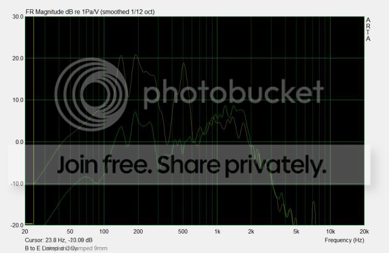
Below is a graph comparing the standard BBC design method using 9mm birch ply with damping vs. the same thing with 'cross-links' in place. It can be seen that the cross-links drastically reduce low-mid resonances by at least -15dB while only adding about 2db to the higher frequencies, so I'd say they are doing exactly what we wanted :)

9mm-Linked-vs-Damped-Only.jpg
 
Version 1 passive crossover now constructed and it sounds very similar to the software emulation :) Next it needs to be tested to see just how close it really is and tweak the parts slightly.

XoverV1.jpg
 
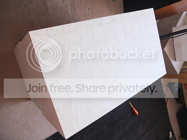
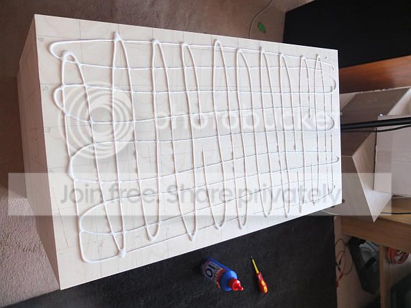
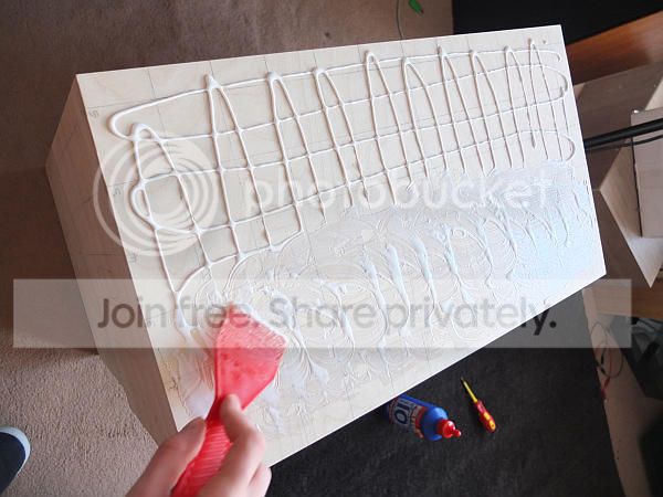
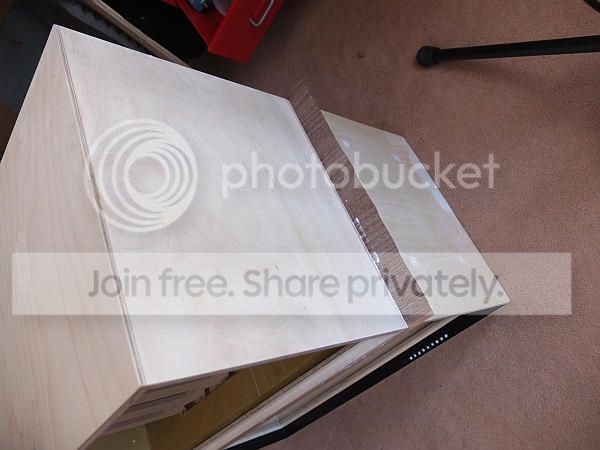
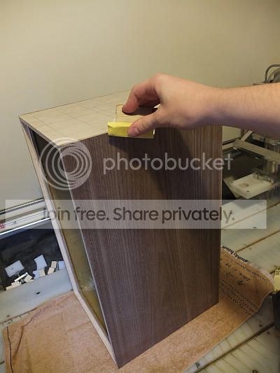
Veneering of the final prototype! I've chosen American Black Walnut for this pair. I wanted to try a couple of different glue methods to see which worked best and it seems like fast set PVA wins out. The nice thing is, if there is any part that didn't set flat you can melt and re-cure it with a hot iron. super strength contact adhesive also worked well but gave less ability to fix the final blips after it was set. A veneer softening mist spray also helps greatly :)

I'll build a screw-press for the next pair, but bottom is tired from sitting on the speakers so much! :D

Veneer1.jpg

Veneer2.jpg

Veneer3.jpg

Veneer5.jpg

Veneer6.jpg


(I glued them in my living room so i could use the computer while I sat on them, haha)
 
Oh, the passive crossover worked exactly as predicted first time! I still tweaked it a little when I decided to change the tweeter face-plate for better phase alignment though. Driver integration between mid and tweeter is even better than the Kensai now :eek:
 
Here is an interesting way to fix bubbles in veneer. As you can see there were a few places where this sheet didn't glue down evenly all over and needed some work. I applied some slightly diluted PVA under each bubble like this, spread it around and let it set. Then the next day I used the iron to re-heat the PVA and glue the bubbles flat. :)

b1832e55-c336-4be0-afdb-b54dd04681c4.jpg


Veneerfix2.jpg
 

Latest posts

Back
Top